Photographic Flash Meter
Most modern cameras come with a one-click auto-mode that gives decent results more often than not. Many situations however require a shot and lighting setup more complex than your basic in-door party picture taken with a pop-up flash. Here is where an external light meter comes into play.
The one described in this project has two modes of operation – ambient light meter and flash meter. In either case the device easily copes with both incident and reflected light, caustics, diffuse light and other complex lighting setups. With a test flash shot the exposure is measured and the camera can then be set to the calculated parameters and a real shot can be made tuned to perfection.
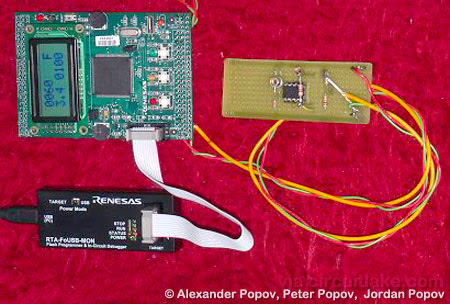
The project’s hardware consist of Siemens BPX65 photodiode, Microchip’s MCP601 Opamp, M32C/84 microcontroller kit and MAX232 IC RS-232 Driver.
How It Works?
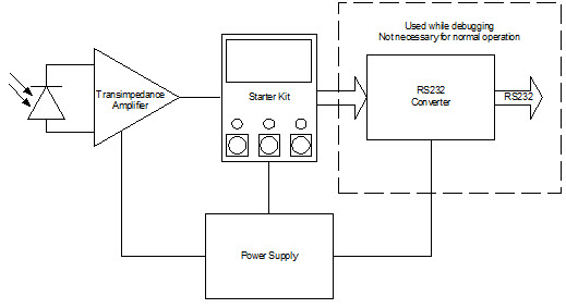
The block diagram of the meter is below. Light (ambient or flash) hits the photo-diode, its the photo-current is amplified by the transimpedance amp and converted to a voltage. This is then sampled at the M32C/84 microcontroller and the integral light intensity for the duration of the shot is calculated. The Starter Kit features three buttons and three LEDs (apart from the reset and power) which are used for interfacing with the system, with visual feedback on the LCD.
The device performs very well as demonstrated by some test shots, although it doesn’t really stress the M32C to its full potential and leaves a lot of room for further improvements, such as controlling slave flashes, flash vs. ambient metering, spot metering etc.