Automatic Volume Control System
The project shows you how to build an automatic volume control system for TV-sets, home audio systems, etc. The system measures current volume level from Audio AUX output and controls audio volume by Infrared commands. The idea is simple – in many situations TV-set user has to adjust the volume: when he or she watch louder part of the movie and do not want disturb sleeping child, when changing channel – channels usually have different volume level and when advertisements are transmitted (they are usually transmitted with significantly higher audio level – which is very annoying). In those and many other situations TV watcher adjusts volume because it is not kept and constant level by the senders. This project is try to make some of those adjustments automatically.
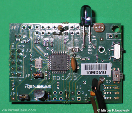
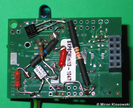
The system has been built over the SKP8Cmini13 Starter Kit. The system is equipped with PIN photodiode, IR LED, and the audio plug which is to be connected to audio-out socket in the TV-set. PIN photodiode is used only during configuration to capture IR commands from TV-set’s remote controller: Volume-UP and Volume-DOWN. There is no need to change TV-set’s internal circuits. It is a simple, battery powered device. IR commands can be learned from original TV’s remote controller. This feature makes the system compatible with probably any TV-set with IR remote control system. The system does not use any feedback – it corrects TV’s audio level using unregulated audio AUX output (speaker output shouldn’t be used here). Volume can also be over regulated – louder parts will be adjusted to volume lower than normal.
Main system concepts and ideas:
- IR learning system which allows to learn any IR sequence assuming that amplitude pulse modulation with constant frequency is used. Carrier frequency can be from about 20 kHz to over 60 kHz. Learning subsystem is very simple – it uses only one PIN photodiode and one resistor. The working range of the receiver is about 1 to 5 cm.
- Learning system uses TimerX which supports an interesting Pulse Period Measurement Mode.
- Learned IR sequences are written to flash memory to be later used to transmit IR commands to TV-set.
- To send IR commands TimerX is used in Pulse Output Mode.
- To measure peak value of audio signal simple peak value detector with Schottky diode and A/D converter (AN2) is used.
- Vref is connected to Vcc – it is therefore unstable and depends on battery voltage. To measure the battery voltage (and calculate corrections to audio measurement) 2.5 V reference voltage source connected to AN3 is used.
- The system is designed to be very power efficient – it wakes up periodically (10 times per second) for a moment, and between those wake up events the system current is only about 50 uA. Periodic wake up have been implemented using TimerY clocked from low speed internal oscillator. Total average current consumption of working system is about 150 uA.