Simple DC Dummy Load
This project shows you how to build a simple constant current sink which can be used to simulate a DC dummy load. It can help you test cheap DC-DC converters to see if they really put out the amount of current as advertised. The circuit is quite simple, a voltage follower or buffer using opamp.
The reference voltage is created by the trimmer potentiometer, which draws its power from a 5V regulator. Instead of using the output of the opamp as the feedback, the voltage drop across the shunt resistors is used. The opamp drives the MOSFETs. As the shunt resistor is small a 2nd opamp is inserted into the control loop to pre-amplify that voltage. Otherwise the output voltage of the trimmer-pot would have to be small.
To prevent unwanted oscillations the output of the opamps is fed back into the inverting inputs using a small ceramic capacitor on both opamp stages. This clamps the AC gain to 1. Inevitable losses in the system reduce any unwanted AC signal to naught. The MOSFET driving opamp adjusts its output in such a way that the current through the shunt resistors matches the set current.
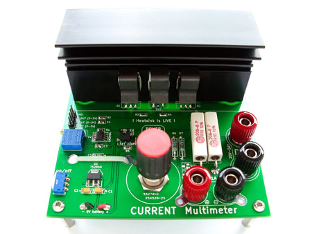
Project specs: 20V, 5A, 20W continuous dissipation, reverse polarity protection, 4mm banana-type binding posts for easy multimeter and load connection, current calibration with a 25-turn trimmer, 10-turn wire-wound potentiometer to set the current.